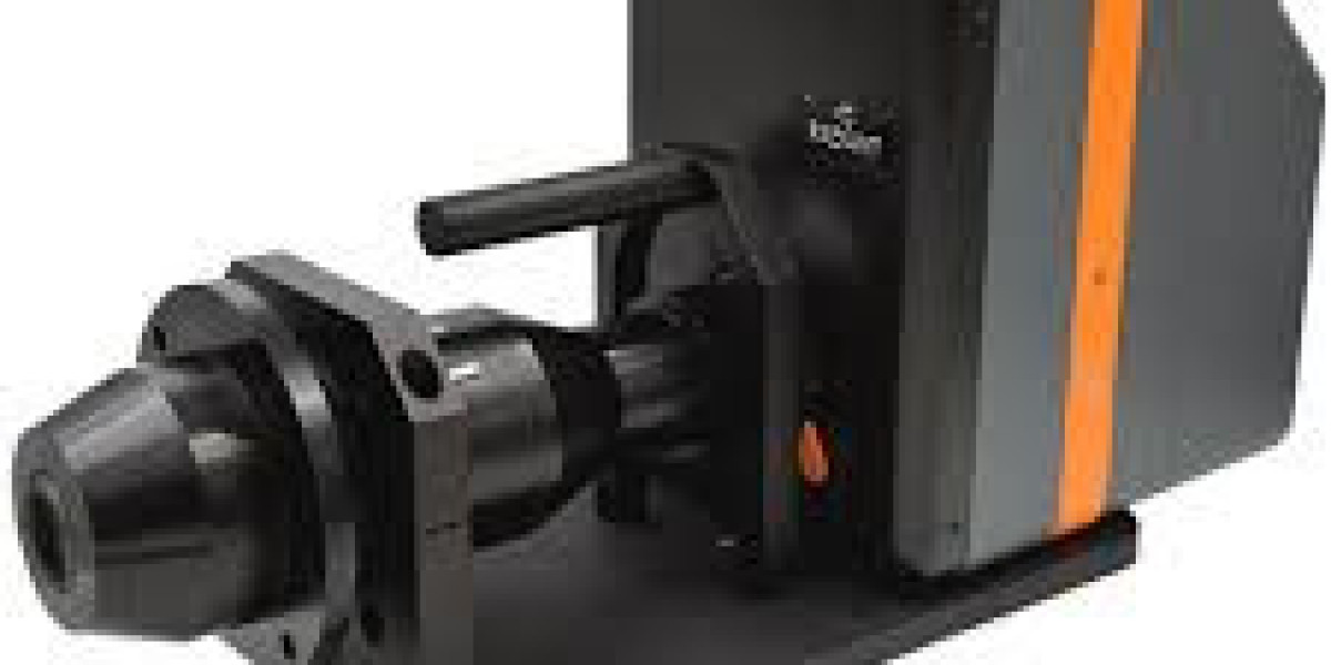

In the high-precision world of 2026 display manufacturing, the conoscope lens is an indispensable tool. It allows engineers to capture the full viewing angle characteristics of a display (luminance, color, and contrast) in a single shot by mapping angular information into spatial information on a sensor.
However, as Micro OLED and Micro LED displays reach unprecedented pixel densities and wider emission angles, the standard conoscope lens is hitting a technical limit. For B2B suppliers and quality control labs, the problem isn't the software—it’s a physical failure in Numerical Aperture (NA) matching and stray light suppression.
The NA Mismatch: Missing the "Edge" Data
The most critical specification of a conoscope lens is its Numerical Aperture. The NA determines the maximum viewing angle the lens can "see."
The Problem: Many legacy conoscope lenses have an NA of $0.6$ or $0.8$, limiting the measurement to $\pm60^{\circ}$ or $\pm70^{\circ}$. Modern VR and automotive displays require accuracy out to $\pm85^{\circ}$ or more.
The Result: If the display's emission angle exceeds the lens's NA, the edge data is "vignetted" or lost entirely. This leads to false reports on color shift and luminance drop-off at wide angles, which is a catastrophic failure in B2B compliance.
The 2026 Solution: High-end manufacturers are now moving toward Ultra-High NA ($0.95+$) Fourier Lenses. These require complex aspheric elements to maintain a flat image plane across the entire angular range without distorting the data.
Stray Light and the "Veiling Glare" Crisis
Because a conoscope lens captures light from all angles simultaneously, it is highly susceptible to internal reflections, known as stray light or veiling glare.
The Mechanism: High-intensity light from the center of the display reflects off the internal lens barrels or the sensor itself and "bleeds" into the wide-angle data zones.
The Symptom: This creates an artificial "haze" in the measurement data, making the display's contrast ratio look much worse than it actually is.
The Technical Fix: Solving this requires Micro-Baffled Lens Barrels and specialized anti-reflective coatings that are effective at extreme angles of incidence. In 2026, a conoscope lens without dedicated stray light suppression is considered an amateur tool.
Working Distance and the Pupil Alignment Bottleneck
The "Exit Pupil" of a conoscope lens must perfectly align with the "Entrance Pupil" of the display or the human eye's position.
The Challenge: Many high-performance displays have a recessed surface (e.g., inside an AR/VR headset). If the conoscope lens has a short working distance, it cannot get close enough to the display to capture the full angle.
The Failure: If the alignment is off by even $0.5$ mm, the angular mapping shifts, resulting in "keystoned" data where $0^{\circ}$ (the center) is no longer the center of the measurement.
B2B Standard: 2026 high-end systems now utilize Integrated Laser Alignment Sensors to ensure sub-micron positioning between the lens and the display panel before a single measurement is taken.
Chromatic Aberration in Fourier Mapping
In conoscopy, the lens performs a Fourier transform to map angles to pixels. If the lens has lateral chromatic aberration, different colors will be mapped to slightly different angular positions.
The Impact: This results in "false color" data at the edges of the measurement. You might see a blue shift in the data that doesn't actually exist on the display, leading to unnecessary (and expensive) calibration changes in the production line.
The Engineering Solution: Solving this requires Apochromatic Fourier Designs using Low-Dispersion (ED) glass. This ensures that the Red, Green, and Blue wavelengths all "land" on the exact same pixel for any given angle.
Geometric Distortion in Angular-to-Spatial Mapping
For the data from a conoscope lens to be useful, the mapping must be perfectly linear (e.g., $1$ mm on the sensor equals $10^{\circ}$ of angle).
The Problem: Non-linear distortion (barrel or pincushion) in the lens causes the angular data to "stretch" or "compress" at the edges.
The Result: This makes the viewing angle look wider or narrower than it truly is.
The Requirement: In 2026, B2B procurement requires a Distortion Calibration Map for every individual lens unit. Software can compensate for some error, but a lens with low native distortion is the only way to ensure the data is "audit-proof."